User Tools

Site Tools


Lines

Introduction

Hexagon offers several types of line and curve tools, which you can use alone or combined to create the lines which can then be used to make simple or complex surfaces. There are many tools in the Surface Modeling tab which use lines or curves as their starting base.

You can draw open or closed curves. Open curves can be combined with others by using composite curves.

Rectangle

The rectangle tool lets you create a rectangle by defining its two opposite corners.
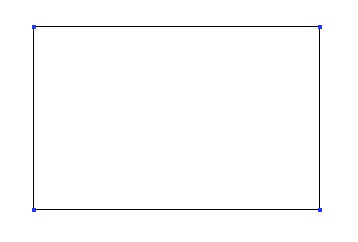
rectangle_tool_example.jpg

Usage:

  • Select the rectangle tool in the Lines tool palette.
  • Set the first corner by clicking a point in the 3D workspace or by entering its coordinates in the object properties palette.
  • Do the same to set the opposite corner or enter the dimensions of the rectangle in the tool properties palette.

Square

The square tool lets you create a square by defining its two opposite corners, and the Hexagon software constrains the height and width together.
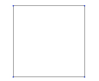
square_tool_example.jpg

Usage:

  • Select the square tool in Lines sub-palette.
  • Set the first corner by clicking a point in the 3D workspace or by entering its coordinates in the object properties palette.
  • Do the same to set the opposite corner or enter the dimensions of the square in the tool properties palette.

Circle

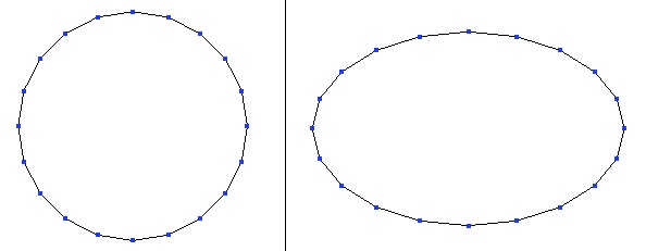
The circle tool lets you create a circle or ellipse by clicking on a start and finish point, followed by the following options.

Circle From the Center

circle_from_center_tool_example.jpg
Left: a circle. Right: an ellipse.

Usage:

  • Select the circle from the center tool in the Lines tool palette.
  • Click in the 3D workspace to define the start of the circle or by entering its coordinates in the object properties palette.
  • A second click defines the size, or you can enter the dimensions of the circle in the tool properties palette.
  • You can define the number of points that make up the circle by entering a number in the tool properties palette, or by typing + or - on the numbers pad of the keyboard.
  • Validate the creation of the circle

Circle From the Basis

circle_from_center_tool_example.jpg
Left: a circle. Right: an ellipse.

Usage:

  • Select the circle from the basis tool in the sub-palette of the Lines tool palette.
  • Click in the 3D workspace to define the start of the circle or by entering its coordinates in the object properties palette.
  • A second click defines the size, or you can enter the dimensions of the circle in the tool properties palette.
  • You can define the number of points that make up the circle by entering a number in the tool properties palette, or by typing + or - on the numbers pad of the keyboard.
  • Validate the creation of the circle.

Circle From the Diameter

Usage:

  • Select the circle from diameter tool in the sub-palette of the Lines tool palette.
  • Click in the 3D workspace to define the start of the circle or by entering its coordinates in the object properties palette.
  • A second click defines the diameter, or you can enter the dimensions of the circle in the tool properties palette.
  • You can define the number of points that make up the circle by entering a number in the tool properties palette, or by typing + or - on the numbers pad of the keyboard.
  • Validate the creation of the circle.

Remark:

  • Use the shift key to snap to points already in the scene for the creation of new lines.


Circle From Three Points

Usage:

  • Select the circle from three points tool in the sub-palette of the Lines tool palette.
  • Click in the 3D workspace to define the first point of the circle or by entering its coordinates in the object properties palette.
  • Click again to define the second point, or enter the dimensions of the circle in the tool properties palette.
  • Click again to define the third point, or enter the dimensions of the circle in the tool properties palette.
  • You can define the number of points that make up the circle by entering a number in the tool properties palette, or by typing + or - on the numbers pad of the keyboard.
  • Validate the creation of the circle.

Remark:

  • Use the Shift key to snap to points already in the scene for the creation of new lines.


Arc

The arc tool lets you create a section of a circle or ellipse.
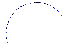
arc_tool_example.jpg

Usage:

  • Select the arc tool, in the Lines tab of the modeling palette.
  • Select the arc type in the tool options palette.
  • Validate the tool to finish the operation

or

  • Select in the Lines sub-palette the arc type you want to create.
  • The five options for creating arcs are created in the order indicated by their title.
  • In each case it is possible before validation to modify the number of points that make up the arc by entering a number in the tool properties palette, or by typing + or - on the numbers pad of the keyboard.
  • Validate the tool to finish the operation

Remark:

  • To edit an arc, use the stretch tool in the Utilities tab.

Center, Start/Radius, Angle

Remark:

  • This arc cannot be used to make a composite curve, because it starts from the center and not from a point on the arc.


Start, Center/Radius, Angle


Start, End, Middle


Start, End, Center/Radius

Remark:

  • An option to this arc tool lets you create an opposite arc.


Start, End, Tangent


Polyline

The polyline tool lets you create a series of straight lines by placing points in your scene.
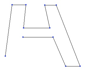
polyline_tool_example.jpg
The polyline tool lets you create quickly polylines.

Usage:

  • Select the polyline tool in the Lines tool palette.
  • Click in the 3D workspace to define the first point of the polyline or enter its coordinates in the object properties palette.
  • Repeat the first step as much as needed.
  • If necessary, hold down the Shift key while clicking on your first point to close the polyline.
  • Validate the creation of the polyline when finished.

Options:

  • Close: Connects the last point with the start point, the same as holding down the shift key.

Remark:

  • A closed polyline cannot be used in a composite curve.

Bézier

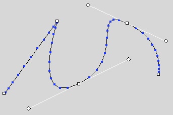
The Bézier tool lets you create straight lines and curved lines with precise control over the tangents and the curves. With this tool you can create complex lines without the need of composite curves.
bezier_tool_example.jpg
A Bézier curve with a corner point and two handles.

Usage:

  • Select the Bézier curve tool in the Lines tool palette.
  • Click in the 3D workspace to define the first point, using one of these two methods:
    • A short click to create a corner point.
    • Click and drag to pull out a Bézier handle.
  • Create your second point, using the same 2 methods. You can edit your curve using the same tool:
    • Click and drag on a handle to change the curve that is affected by that point.
    • Click and drag on the point to move it.
    • Ctrl + click and drag on a handle to break the symmetry of the Bézier handles.
    • Ctrl + Shift + click on a handle to retract it, and delete its prescribed curve.
    • Ctrl + Shift + click on a point to delete it.
  • To close a polyline, use one of these two methods:
    • Click on the starting point to close it with a corner.
    • Click and drag on the starting point to pull out the Bézier handles.
  • You can now validate the curve, or continue to modify the points and handles as shown above.

Remark:

  • To edit a Bézier curve, use the stretch tool in the Utilities tab.


Interpolated Curve

This tool allows you to draw a smooth curve by creating a control polyline of at least 3 points. The curve goes through the points of the polyline.

interpolated_curve_tool_example.jpg
An interpolated curve with its control polyline. Compare with the curve tool.

Usage:

  • Select the interpolated curve tool in the Lines tool palette.
  • Click in the 3D workspace to define the first point of the control polyline for the interpolated curve, or by entering its coordinates in the object properties palette.
  • Repeat this step as many times as necessary.
  • If needed, close the polyline using the close option in the tool properties palette, or by holding down the Shift key while clicking on the start point.
  • Validate the creation of the interpolated curve when finished.

Options:

  • Close: connects the last clicked point with the starting point of the interpolated curve.
  • Range: modify the number of points of the curve.

Remark:

  • The creation of a composite curve is not possible with a closed interpolated curve.

Curve

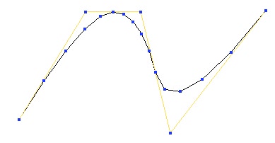
This tool allows you to draw a smooth curve by creating a control polyline of at least 3 points. The curve touches the segments but not the points (except for the first and last points) of the control polyline.
curve_tool_example.jpg
A Curve with its control polyline. Compare with the interpolated curve.

Usage:

  • Select the curve tool in the Lines tools palette.
  • Click in the 3D workspace to define the first point of the control polyline for the curve, or by entering its coordinates in the object properties palette.
  • Repeat this step as many times as necessary.
  • If needed, close the polyline using the close option in the tool properties palette, or by holding down the Shift key while clicking on the start point.
  • Validate the creation of the curve when finished.

Options:

  • Close: connects the last clicked point with the starting point of the curve.
  • Range: modify the number of points of the curve.

Remark:

  • The creation of a composite curve is not possible with a closed curve.

Composite Curves

The composite curve is a collection of open curves, connected to one another, letting you make complex forms without welding the curves together and losing the dynamic aspect of certain curves (such as control points/polylines). If the current selection is open, when creating a new curve, three options allow you to connect or not the new curve with the current selection to create or add to a composite curve.

composite_curve_tool_example.jpg
A Composite curve made of a curve and an arc of circle.

Usage:

  • Select an existing open curve.
  • Select a drawing tool.
  • Then either:
    • Select the option “do not connect” if you want the two curves to be independent
    • Or select “connect to the beginning of the last selected curve” to make the new curve connect to the start of the existing curve.
  • Select “connect to the end of the last selected curve” to make the new curve connect to the end of the existing curve.
  • Then either:
    • Select a new tool without leaving the current tool: the Hexagon software validates the current curve, and activates the new tool automatically connecting the new line with the existing one.
    • Or validate the tool to finish the curve, once the different options have been chosen, if needed.

Remark:

  • To edit a composite curve, use the stretch tool in the Utilities tab.


2D Text

The 2D Text tool creates outlines of type.

2d_text_tool_example.jpg
A 2D Text object.

Usage:

  • Select the 2D text tool in the Lines tools palette.
  • Click in the 3D workspace to define the starting point of the text.
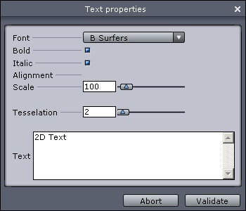
  • The 2D text editor appears.
  • The font menu lets you choose your typeface.
  • Bold and italic applies these styles to the chosen typeface.
  • Alignment lets you choose center, left and right starting at the reference point.
  • Scale lets you enlarge or reduce the generated outline of the type.
  • Tesselation lets you increase or decrease the number of lines used to describe a curve. The higher the number of tesselation, the smoother the text will be.
  • The text zone lets you type in the text to be created. Hard returns are done with the Enter key.
  • Validate the tool by clicking on the Validate button.

2d_text_editor.jpg
The 2D Text editor.

Remark:

  • Hexagon uses only the TrueType fonts installed in the system folder of the computer.
  • For efficiency and further editing, avoid giving a too high tesselation (10 maximum).

Helix

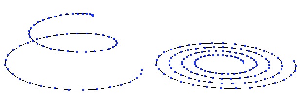
The helix tool creates a spiral.

helix_tool_example.jpg
Two kinds of helix.

Usage:

  • Select the helix tool in the Lines tools palette.
  • Click in the 3D workspace to define the start point for the helix, or enter its coordinates in the object properties palette.
  • Define the radius of the starting spiral, or enter a value in the tool properties palette. The created spiral is perpendicular to the active view.
  • Move your mouse to define the height of the spiral, or enter a value in the tool properties palette.
  • Click to validate your first spiral.
  • Define the desired number of spirals in the tool properties palette.
  • Define the number of points making up the spiral in the tool properties palette.
  • Validate the tool to create the spiral.

Keyboard shortcut: Space bar: changes the axis constraints.


2D Symmetry

The 2D Symmetry tool lets you rapidly create a copy of the active line by mirroring the X, Y or Z axis, and connecting them if needed.

2d_symmetry_tool_example.jpg
Left: the original curve. Right, the result of the symmetry.

Usage:

  • Select a line or curve to mirror.
  • Select the 2D Symmetry tool in the Lines tool palette: An axis appears, with a visual indicator showing a mirrored point on this axis.
  • Choose the connection options if needed.
    • Do not connect: The two lines are independent.
    • End-Start: connects the end of the line with the start of the mirrored line.
    • Start-End: connects the start of the line with the end of the mirrored line.
    • Connect all: connects the start and end of each line.
  • Click to define the center of the mirror. Hold down the Shift key to snap to a point already in the scene.
  • Your curve is mirrored and connected following your chosen options.

Keyboard shortcut: Space bar: changes orientation of the mirror.

Curve Extraction

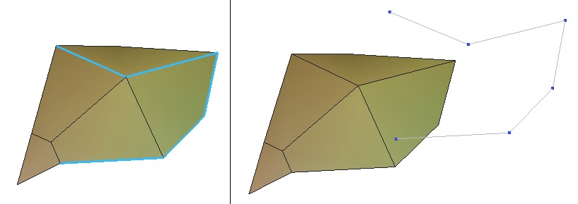
The curve extraction tool lets you create a curve from a selection of points on a surface mesh.
curve_extraction_tool_example.jpg
Left: the selected edges. Right: the extracted curve.

Usage:

  • Select the item from which you want to extract the curve.
  • Use the select points mode in the selection palette.
  • Select on the mesh one or several points that are connected between them (they have to be continuous, representing an open or closed contour).
  • Click on the curve extraction tool in the sub-palette of the Lines tool palette, and a polyline will be created out of each selected point, if your selection is valid.

Curve Offset

The curve offset tool creates a curve next to the original curve at a given distance, which stays parallel to the original curve for the length of the curve.

curve_offset_tool_example.jpg
Left: the original curve. In the middle: an external offset. Right: an internal offset.

Usage:

  • Select the curve that you want to be offset.
  • Select the offset curve tool in the Lines tool palette.
  • The tool creates the offset curve with a default amount. By using the tool properties palette you can change the offset amount and whether the offset is interior or exterior.

Keyboard shortcuts:

  • +/-: More/less offset.
  • Space bar: Choice of orientation.

Insert Points

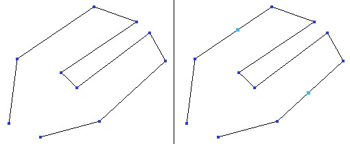
The insert points tool lets you fine-tune a curve, or its control polyline.
insert_points_tool_example.jpg
Left: the original curve. Right: the two inserted points.

Usage:

  • Select the line or curve that you want to add a point to.
  • Select the insert points tool in the Lines tool palette.
  • Click on the segment of the line you want to insert a point to. The point will be added on the clicked spot.
  • Repeat as many times as needed.
  • Validate the tool to stop inserting points.

Remark:

  • By default, the points insertions are performed on the lowest dynamic geometry level.

Polyline Tesselation

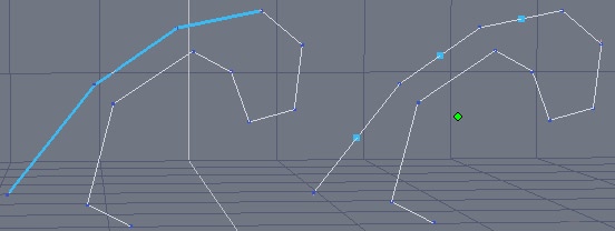
This tool divides a segment of a polyline in its middle, from a previously done selection. This function is quite similar to the “Insert point” tool, but can be used on multiple selections.
polyline_tesselation_tool_example.jpg
On the left, the original polyline with 3 edges selected. On the right, the same edges subdivided and the vertices selected.

Usage:

  • Select the polyline you want to edit.
  • Choose edge selection mode and select the edges to subdivide.
  • Click on the line tesselation tool, in the “Lines” tab.
  • The selected edges are automatically subdivided by their middle.

Remark:

  • This tool can be used to control curves of objects built with the dynamic geometry.

Close

The close tool closes open curves.

close_tool_example.jpg
Left: the open curve. Right: the closed curve.

Usage:

  • Select the curve you want to close.
  • Click on the close tool in the sub-palette of the Lines tool palette.
  • If the curve is open, it will now be closed.

Remark:

  • This operation deletes the dynamic geometry or composite curve.

Reverse a Curve

The reverse a curve tool lets you redefine the curve's starting point. This is a useful tool when using composite curves or connections.

Usage:

  • Select the curve you want to reverse the direction.
  • Click on the reverse a curve tool in the sub-palette of the Lines tool palette.
  • A little white circle showing the start of the curve appears. Click on the other end of the curve to move this indicator to the other end of the curve, thereby defining that end as the new start of the curve.
  • The direction of the curve is now changed.