User Tools

Site Tools


3D Primitives

Introduction

3D Primitives are objects created by Hexagon to serve as a basis of modeling: whether creating simple or complex objects, these forms can serve as a good starting point. However, keep in mind once these forms are created, they are no longer editable in the sense of changing the parameters that are available at their creation.

For example, once the creation of a primitive sphere is validated, the amount of tesselation can no longer be edited. Nevertheless, these shapes could still be affected by other tools, such as smoothing.

Cube

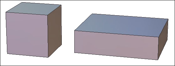
The cube tool creates cubes and 3D parallelepipeds.
cubes.jpg
Left: a perfect cube. Right: a 3D parallelepiped.

Usage:

  • Select the cube tool in the 3D Primitives tab.
  • Click in the 3D workspace to create the cube, or by entering its coordinates in the object properties palette. If necessary, in the tool properties palette choose create from center and not by basis (the default).
  • Move the mouse to define the size of the cube and validate the tool, or enter the dimensions in the tool properties palette.
  • Once the cube has been created, hit the +/- keys to tesselate the cube, or manually enter the tesselation level in the tool properties palette.

Remark:

  • It is also possible to drag-and-drop the tool icon into the 3D scene, which will create the primitive located where you will have released the mouse button. The primitive dimensions will be automatically defined according to the 3D View size.

Sphere

The sphere tool creates spheres using different topologies.

spheres.jpg
The different kinds of spheres.

Usage:

  • Select the sphere tool in the 3D Primitives tab.
  • Click in the 3D workspace to create the sphere, or by entering its coordinates in the object properties palette. If necessary, in the tool properties palette choose create from center and not by basis (the default).
  • Move the mouse to define the size of the sphere and validate the tool, or enter the dimensions in the tool properties palette.
  • In the tool properties palette, define the number of points that make up a half diameter of the sphere, as well as the vertical/horizontal pucker and bloat (an in/out distortion around the hemisphere or vertical axis).

Options:

  • Pole-sphere (default)
  • Geodesic sphere.
  • Geodesic sphere based on an icosahedron
  • Geodesic sphere based on an octahedron

Remark:

  • It is also possible to drag-and-drop the tool icon into the 3D scene, which will create the primitive located where you will have released the mouse button. The primitive dimensions will be automatically defined according to the 3D View size.

Keyboard shortcuts: +/- Increase/reduce the number of points making up the half diameter of the sphere.

Facet

The facet tool can make polygonal faces that can be added to the current object or to make a new object if there is nothing currently selected.

Usage:

  • Select an unclosed surface to which you want to add polygons, or deselect everything if you want to create a new object.
  • Select the facet tool in the 3D Primitives tab.
  • Click in the scene to define the starting point of the polygon. If necessary, use the Shift key to snap to an existing point in the scene.
  • Repeat the last step as many times as necessary.
  • Validate the tool to create the polygon by clicking on the Validate button, or the Enter key. It is added to the selected object if there is one, or if not, a new object is created and selected.
  • Repeat the last steps to add new polygons to the selected object.
  • Validate to finish the operation.

Remark:

  • The facet tool uses 3D rulers. You can input coordinates of points in space or snap to existing ones using the Shift key.

Keyboard shortcut: Space bar: Lets you apply a vertical or horizontal constraint when you are drawing polygons.


Cone

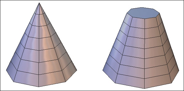
The cone tool lets you create a cone, open or closed.
cones.jpg
Left: a cone. Right: a truncated cone.

Usage:

  • Select the cone tool in the sub-palette of the 3D Primitives tab.
  • Click in the 3D workspace to create the cone, or by entering its coordinates in the object properties palette.
  • Move the mouse to define the size of the cone base from its center and validate, or enter the dimensions in the tool properties palette.
  • Move the mouse to define the height of the cone and validate, or enter the dimensions in the tool properties palette. If needed, enter a value for the radius of the cone to create a cone without a tip.
  • White edges show the openings, which you can click on to close (indicated by the edge turning red).
  • In the tool properties palette define the number of horizontal and vertical sections making up the cone and validate the tool to create the cone.

Options:

  • Close all: This option closes all openings.

Remark:

  • It is also possible to drag-and-drop the tool icon into the 3D scene, which will create the primitive located where you will have released the mouse button. The primitive dimensions will be automatically defined according to the 3D View size.

Keyboard shortcut: +/- Increase/decrease the number of sections.

Cylinder

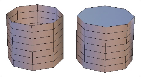
The cylinder tool creates open or closed cylinders.
cylinders.jpg
Left: an open cylinder. Right: a closed cylinder

Usage:

  • Select the cylinder tool in the sub-palette of the 3D Primitives tab.
  • Click in the 3D workspace to create the cylinder, or by entering its coordinates in the object properties palette.
  • Move the mouse to define the size of the cylinder base from its center then validate, or enter the dimensions in the tool properties palette.
  • Move the mouse to define the height of the cylinder and validate, or enter the dimensions in the tool properties palette.
  • White edges show the openings, which you can click on them to close (indicated by them turning red).
  • In the tool properties palette define the number of horizontal and vertical sections making up the cylinder and validate the tool to create the cylinder.

Options:

  • Close all: This option closes all openings.

Remark:

  • It is also possible to drag-and-drop the tool icon into the 3D scene, which will create the primitive located where you will have released the mouse button. The primitive dimensions will be automatically defined according to the 3D View size.

Keyboard shortcut: +/- Increase/decrease the number of sections.

Platonic Shapes

Platonic shapes are primitives corresponding to certain mathematical principals, which would be difficult to model from scratch. Hexagon proposes four kinds platonic shapes: tetrahedron, octahedron, icosahedron and dodecahedron.

platonic_shapes.jpg
From left to right: the different kinds of platonic shapes.

Usage:

  • Select the desired platonic shape in the sub-palette of the 3D Primitives tab.
  • Platonic shapes are created in the same way as cubes.

Remark:

  • It is also possible to drag-and-drop the tool icon into the 3D scene, which will create the primitive located where you will have released the mouse button. The primitive dimensions will be automatically defined according to the 3D View size.

Grid

The grid tool lets you draw a grid made up of cells. The proportions of the first cell define the proportion of the grid.

grids.jpg
Three kinds of grids with more or less cells.

Usage:

  • Select the grid tool in the Vertex Modeling tab.
  • Click in the 3D workspace to create the first corner of the cell of the grid, or by entering its coordinates in the object properties palette.
  • Move the mouse to define the opposite corner of the cell and validate, or enter the dimensions in the tool properties palette.
  • Move the mouse to create other cells as the bounding box expands to accommodate them, then validate, or enter the number of desired cells in the tool properties palette in lines (U) and columns (V).

Remark:

  • It is also possible to drag-and-drop the tool icon into the 3D scene, which will create the primitive located where you will have released the mouse button. The primitive dimensions will be automatically defined according to the 3D View size.

3D Text

The 3D text tool puts type in volume by extruding the font outlines.

text.jpg
A 3D text primitive.

Usage:

  • Select the 3D Text tool in the sub-palette of the Vertex Modeling tab.
  • Click in the 3D workspace to define the starting point of the text.
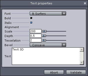
  • The 3D Text editor appears.
  • The font menu lets you choose your typeface.
  • Bold and italic applies these styles to the chosen typeface.
  • Alignment lets you choose center, left and right starting at the reference point.
  • Depth sets the amount of extrusion of the type.
  • Scale lets you enlarge or reduce the generated outline of the type.
  • Tesselation lets you increase or decrease the number of lines used to describe a curve. The higher the number of tesselation, the smoother the text will be.
  • Bevel lets you apply a bevel to the face and back of the type.
  • The text zone lets you type in the text to be created. Hard returns are done with the Enter key.
  • Validate the tool by clicking on the Validate button.

text_editor.jpg
The 3D text editor.

Remarks:

  • Hexagon software uses only the TrueType fonts installed in the system folder of the computer.
  • For efficiency and further editing, avoid giving a tesselation too high (10 maximum)