Table of Contents
DAZ Studio 4.x
- QuickStart Guide PDF
- User Guide PDF
* = Review
There is a donor rig bug that can cause a crash.
Close-fitting clothing can be fitted to a figure using the Transfer Utility, which supplies bones, Face Groups, Region Groups, weight maps, and morphs. But for loose-fitting items, or items with extra movable parts, or articulated props, the rigging will need to be created manually.
Three utilities are used during the process of creating and rigging “Ghost Bones”: the Joint Editor, Polygon Group Editor, and Weight Map Brush. The Joint Editor and Polygon Group Editor steps can be performed in either order, and in fact it may be helpful to switch between the two tools frequently. This tutorial covers the Joint Editor portion of the process.
In general, the process of creating “ghost” bones consists of the following sub-processes:
The TriAx™ rigging system operates differently than the legacy Poser rigging system, though it has some similarities. Like the Poser system, a skeleton of bones is created to match the skeleton of a figure to which the item will be conformed to, or to provide additional controls for unique parts of the figure. Face Groups are created using the Polygon Group Editor which are comparable to Poser's groups. However, Face Groups only allow the end-user to select and manipulate the bones of the skeleton. They do not tie the bones to specific portions of the mesh. Instead, a set of Weight Maps, one for each axis of rotation per bone, describes the influence of each bone on the entire mesh.
Import the model, which should have been constructed to fit the Genesis default figure.
If you wish to model against a non-default “shape” applied to Genesis, please see Modeling Against a Genesis Shape *.
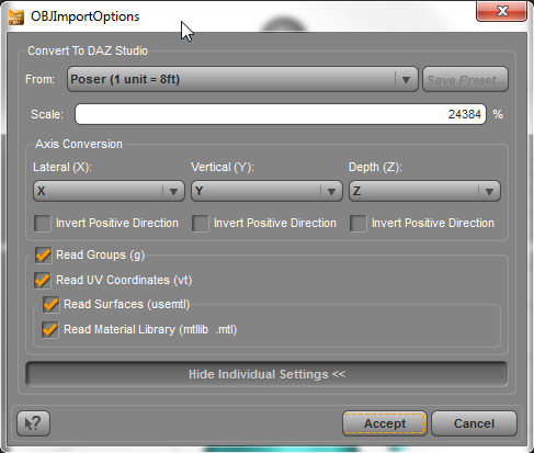
Be sure to match the scale the OBJ was modeled in:
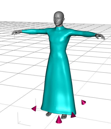
Here is the unrigged figure in our example, a modified version of the Morphing Fantasy Dress.
You can quickly set up a basic rigging for this figure by using the Transfer Utility (from the Options menu of the Scene tab):
![]()
You may leave most of the settings at their defaults. You may find a Projection Template helpful. These are optimized “helper” files that contain weight maps and other data tailored for specific clothing or hair types. In this case, the Dress→Tight template does not add foot and toe bones to the figure, which saves us some time in removing those later.
Save time by checking “Add Smoothing Modifier” and defining the Content Type during this step.
![]()
The results with this rigging are not terrible, but don't match the functionality of the original item. We don't typically want the skirt to move precisely with the legs, which is what the “Dress” template assumes.
![]()
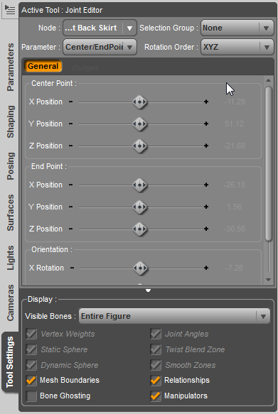
To modify the rigging, we will need to use several tools, including the Joint Editor, the Weight Map Brush, and the Polygon Group Editor. For all of these, we will want to be sure to have the Tool Settings tab in view, shown here with the Joint Editor details.
Activate the Joint Editor tool. If necessary, you will first remove unused bones, such as foot and toe bones if you are rigging a dress. These can be most accurately selected in the Scene tab. You may also find it helpful at this point to hide the Genesis figure and switch to a Smooth Shaded preview.

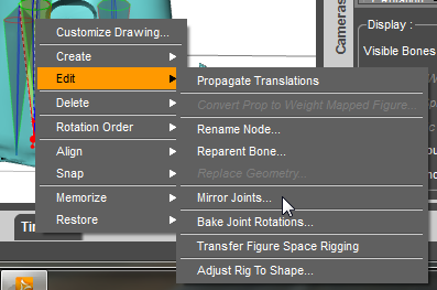
Next, we'll begin to add the new bones, two per side, attached to the end of the Shin bones. Start by selecting the Right Shin bone, and use the context menu to Create a new Child Bone:

Use a consistent naming convention for good ease of use. Additionally, if you name your left and right sets of Ghost Bones by a consistent pattern, prefixed with L and R or similar, you can use the Mirror Joints command to position half of the new bones.
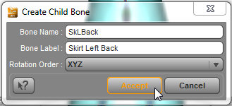
As you create each new bone, you will need to define the Axis Order. (This can be edited later.) The X, Y, and Z parameter dials will each be assigned to a function, depending on the order in which they are listed.
The first axis in the rotation order is twist, spinning around the length of the item without changing its position in space. The X parameter is very often assigned to Twist in upper limbs, which extend along the X axis in the T pose. In core trunk portions of the body and lower limbs, Y is more commonly assigned to Twist.
The second axis indicates “Side to Side” movement, by convention. It is often defined as the Z axis. In the shoulder area, however, where “Front-Back” terminology is used, the Y axis may be assigned to the second position.
The third axis in the list usually indicates a “Bend” in the joint. In the body trunk, this is usually the X axis. For the limbs, it may vary, depending on the orientation of the limbs.
Use this helpful tip to determine which axis order will work best in your situation:
With your hand posed as shown above, imagine yourself “pointing” at a specific bone in the figure from the front view, such that your index finger (Side-Side) would pass through the bone and your thumb is aligned with the length of the bone (the Twist axis), pointing away from the hip. Your remaining fingers should point along the “Bend” axis. The order you want would then be Thumb (1) Index finger (2) and Remaining Fingers (3).
So, for a hip, abdomen or chest of a bipedal figure you would point straight out and the rotation order would be YZX.
For a foot your hand would be pointing down with your thumb extending “forward” and your fingers pointing left (or right!) so the rotation order would be ZYX.
For an arm on a bipedal figure, pointing out to either side, you would point your hand forward and have your thumb pointing left (or right!) along the length of the bone. Your remaining fingers would point up or down, so the rotation order would be XZY.
The bone will be created at the bottom of the Right Shin bone, in a horizontal position:
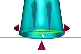
Move the Center Point and End Point of the bone to align appropriately with the facets they will control:

And use the Align Node command to line the bone up with the center and end points.
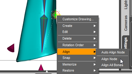
While bones that will move with the wearing figure need to be named exactly the same as those in the wearing figure, extra bones added for control of the mesh may be named according to any consistent standard to provide ease of use for customers.
After aligning the bones on the right side, Select the Right Shin, and use Selected Recursive, Selected to Opposite, and make sure the prefixes you used are included in the semicolon-delimited list:
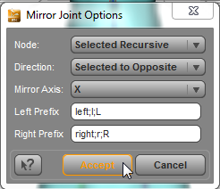
NOTE: The Node Name and Node Label must both use appropriate left/right prefixes for the Mirror Joints command to work.
Memorize your Figure Rigging periodically while working.
Right-Click, Memorize → Memorize Node Rigging

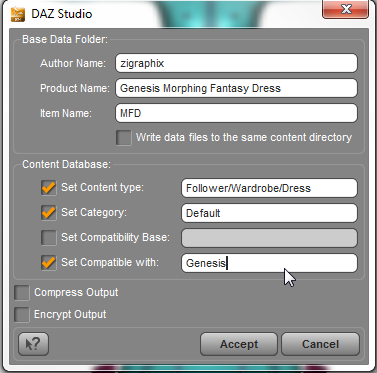
Periodically save your work. Because this will be a weight-mapped conforming figure, it should be saved as a DSF Figure or Prop file.

Some information in the save dialog will be automatically filled in for you, depending on what options you selected while using the Transfer Utility and other tools. Filling in this dialog correctly will help when creating Metadata later.
This process has added a number of new “Ghost” bones to allow more flexible control of the dress movement. In order for these new bones to function, they must be associated with Face Groups using Weight Maps. If you have not yet created Face Groups to match the new skeleton, go to that tutorial next. Otherwise, you can proceed to using the Weight Map Brush.
