User Tools
Site Tools
Sidebar
Advanced Measuring
Summary
In the previous sections, you learned that you can use the regular Scale, Rotate and Translate tools to make your Tailor's Tapes “fit” the areas you want to measure. Sometimes these quick adjustments are not going to be good enough. Now we will cover some more advanced settings that will help you pinpoint areas more precisely and choose some other calculations such as “Area”.
Process Overview
This section will cover the following:
Restrict to Polygon Selection
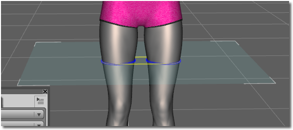
As we saw earlier, the Tailor Tape is very useful in measuring different body areas. What happens when we just want to measure a single thigh? Following the methods above will give us the circumference of both thighs and any space between, as shown in the image below:
What we really want, in this case, is the measurement of the right thigh and nothing else. We could scale the node, finagle and twist it and hope we can fit in just right to get the correct results, or we can use the Restrict to Polygon Selection feature. Let's try that one!
There are a few things we will need to set up, so a good working knowledge of DAZ Studio is recommended, but not required.
- Load your figure into the scene.
- Add a Tailor Tape node named “Thigh” using the process you learned above.
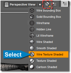
- Change your View to “Wire Texture Shaded” This allows you to see the individual polys of the figure you are working with, which will be very handy in a moment.
- Next, turn on the Polygon Group Editor Tool.
 This will allow you to see and select the polys you want to designate for the Tailor Tape.
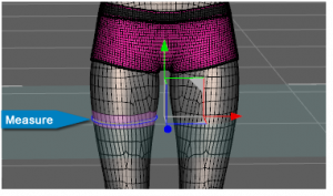
 - Now simply select a group of polys around the thigh, as shown below. Hold down the CTRL key while selecting – You will also need to rotate your camera to select those on the back of the thigh as well.

- With your selection highlighted, go to the Measure Metrics pane and select “Set Target Faces for Tailor Tape node…”
- In the pop up window, choose the appropriate Tailor Tape from the list. (This is where you begin to see the value of naming your nodes appropriately. Once you have several added to your scene, it can get very complicated very quickly.)
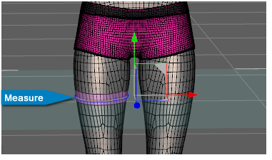
 Now select the “Thigh” Tailor Tape in your scene. As you can see, the polygon selection associated with it becomes a different color. (Pink by default) If you have more than one node in your scene, the associated polys will highlight with their respective node as each is selected. And even better, our “Thigh” node is only measuring the right thigh!

Tip: You can add as many nodes to your scene as you need. Just make sure you name them appropriately. Your life will be much easier, and your blood pressure will thank you.
Compound Measure
Compound Measure allows you to choose two or more nodes to obtain a combined total. This would allow you to figure out the value of an area or volume for example. Here is a simple demo:
- Add a cube to a new scene.
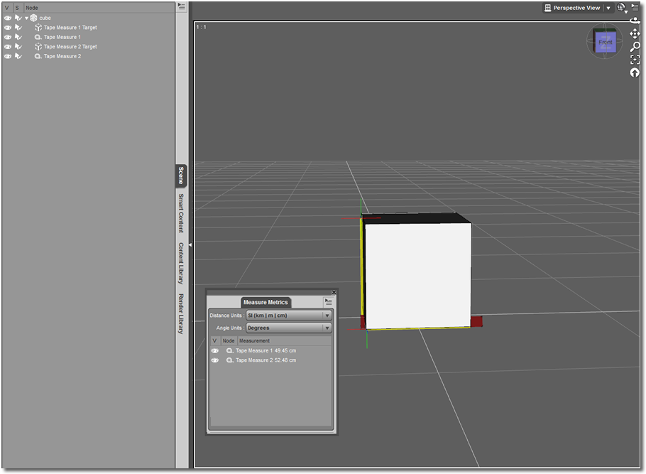
- Set up (2) Tape Measures – One measuring width, and the other height. Use a Null target like you learned in that section. It should look something like the image below, once you are done:

- Now, select both of your Tape Measures in your Measure Metrics pane. (Hold the CTRL key to multi-select.)
- Select “New Measure Metric” in the Measure Metric's menu.
- Choose “Compound Measure” as the type and name it appropriately. Something like ”Area of Cube 1”.
- Hit “Accept”.
You can see a new entry in your Measure Metrics pane. This shows you the total of the combined Tape Measures you selected. But wait a minute… That total seems strange. Let's fix that.

- Select your “Area of Cube” measurement in the Measure Metric pane.
- Go to “Parameters > Measure”.
- Change the Measure Type to “Area”.
There! That looks much better. We now see our result “squared”. You can add a third Tape Measure and set it up to give you the volume of the cube by combining the three Tape Measures, and changing your Compound Measure type to “Volume”.
Using With Rigid Follow Nodes
Using the different Measure Metric nodes when moving and morphing your figures can cause some frustrations. The node may not follow the exact spot you want, such as the top of the head, thus sending you scrambling to make adjustments. In our Tape Measure section above, we measured the height of Genesis, but if we bent her head we had to either use and move a “null” manually, or just let the Tape Measure sit where it was.
Using “Rigid Follow,” we can set our Measure Metric node to follow a specific poly or group of polys we assign as a target. This allows you to pose and morph the figure, while still measuring to the exact same spot. Go ahead and load a figure. We will use Genesis 2 again for this demo.
- 1. Load Genesis in a new scene.
- 2. Change the view to “Wire Texture Shaded” as you did earlier.
- 3. Select the figure's “Head”. (This works best if you first select the Bone in relation to the polys you will be selecting. In this case, the Head.)
- 4. Looking at the top of the figure's head, let's select the 4 center polys using the “Poly Group Editor” tool again.
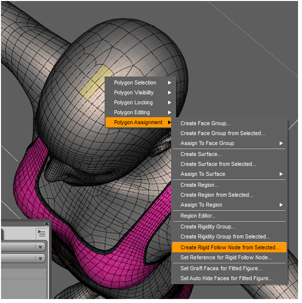
- 5. R-Click the viewport and select “Polygon Assignment > Create Rigid Follow Node from Selected” as shown below:
You should now have a small cross-hair at the center of the 4 polys you used to create your node, as seen here. If you need to adjust the cross hairs or position them on your selection, just drag them via the normal “Translation” tool methods.

- Select your figure.
- Add a new Measure Metric node – Type is: “Tape Measure”. Parent it to the figure.
- Name the Tape Measure node “Height to Head”.
- Select the Tape Measure, and go to Parameters.
- Set the Measure Target to your “Head Top” Rigid Selection. (You will have to browse to the Head to find it.)
Once you do this, you will see the yellow measuring “tape” shoot up to the top of the head where you created your Rigid Follow node. If you bend the head now, you will notice the end of the the Tape Measure now follows those polys.
What did we accomplish? By parenting the Tape Measure to the figure, we ensured the node would follow along with the figure, no matter where we move it in the scene. Also, by assigning our Rigid Follow node as the target, we now have the ability to morph or pose our figure and the tape will stay “attached” right where we put it – As shown here:
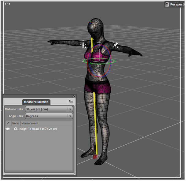
Notice how the yellow tape is now slightly angled to move with the forward bend of the figure's head. It will now follow any other movement or scaling you apply to the figure. Remember, the tape measure will continue to measure in a straight line from point “A” to point “B” just like a “real” tape measure, but this one will not force you to move things out of the way.
Tip: Try changing the height and pose of your figure. Watch how the measure node follows and moves to accommodate your changes. Try the different node types and combine some of the different features you have learned to see what else you can “measure”.
Wrap-Up
For further help, please refer to the main section of the plug-in's documentation:
Or check out some of the Tips and Tricks which include customizing colors and saving assets for future use.
Page Tools
Except where otherwise noted, content on this wiki is licensed under the following license: CC Attribution 3.0 Unported
