Table of Contents
DAZ Studio 4.x
- QuickStart Guide PDF
- User Guide PDF
This page is a WIP. There are likely to be incomplete and or missing steps while the page is being built.
If you have finished Part I, Basic: Rigging Preparation of this tutorial, you are ready to add the Bones to your object, so you can begin Rigging. Part II will walk you through adding Bones, setting up your Hierarchy, and editing the Joints, as well as selecting the type of Weight Mapping you wish to do.
By the time you finish this section, you should be able to:
Before proceeding with the Rigging Articles, it is assumed you have already created a model in the program of your choice, as well as finishing Basic: Rigging Preparation (WIP). The following section will give you instruction on creating the bone structure you will need for Weight Map Rigging.
 To create bones for the model, open up the Figure Set Up Pane in the Main Menu Bar Window > Tabs > Figure Setup. (see Illus. 2)
You can also select the Figure Set Up icon. (see Illus. 3)

 To Load your model, under the Geometry List Column, Right Mouse Click on an empty portion of the column and select Add Geometry. Browse to your OBJ's location and select the model. (See Illus. 4)
 When you select the obj under the geometry list, you will see that all the selection sets you made are listed underneath it. (See Illus 5.) Next, we will create bones that correspond with these selection set names. To do this, drag the obj found under the Geometry List column and drop it onto the Relationships Column directly over Geometry.
 You should now have a list of bones that correspond with the selection sets you made. (See Illus. 6)
The bones that have been created need a Hierarchy. In other words, a parent-child relationship that will create a skeleton. Using your leg as an example, your foot, at the very end of the chain of your leg is a child of your Shin Bone, (and the Shin is considered the parent of the Foot.) As you go up, the shin is a child of the Thigh, and the Thigh is a child of the hip.
Use drag and drop to set up the hierarchy relationships. Drag and drop in Figure Set Up is designed to drag the child bone to the parent bone to set up the hierarchy.
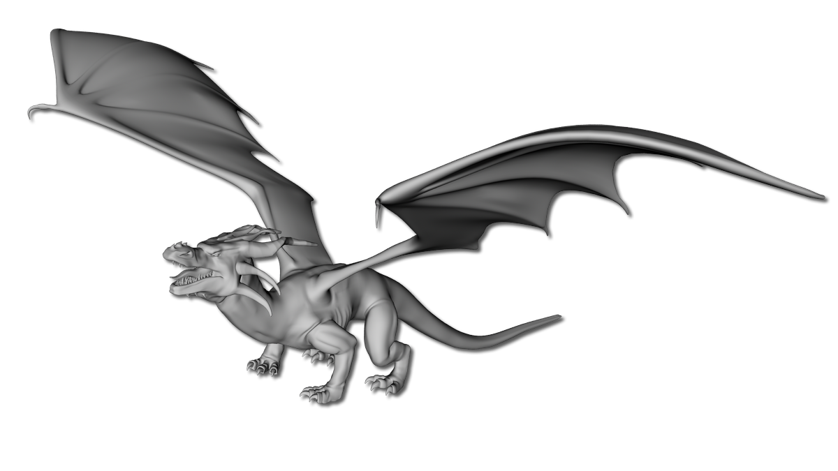
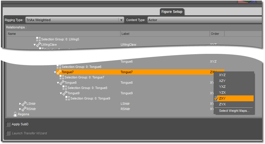
 As an example, drag the L Foot onto the L Shin, the L Shin onto the L Thigh, the L Thigh onto the Hip, to create a hierarchy for a basic figure. The dragon, while not a basic figure, still works on the same principle. Using the Dragon's tongue as an example; which consists of 10 selection sets, Tongue Base (The start of the tongue rooted in the mouth) is the beginning of the hierarchy for the Tongue, then follows Tongue1, thru Tongue9, (Tongue9 being the very end tip of the tongue. (See Illus. 7)
Tongue9 is selected and dragged onto Tongue8, Tongue 8 is selected and dragged onto Tongue7, Tongue 7 dragged to Tongue 6, etc. Until we get to the end where Tongue1 is dragged onto the TongueBase group. So where does TongueBase go? It gets dragged onto the Head group. The Eyes also get dragged to the head group, and the Head gets dragged thru the neck groups, the final neck group gets dragged to the chest group, and the chest group gets dragged, to the hip, the root of this figure. Every chain eventually ends at the root.
When the hierarchy is complete, its time to change the rotation order of the bones. Over to the far right of the Figure Set Up Menu, under the order column, is found a default set up, XYZ.
 The first axis is the Twist Axis, this is the axis that goes lengthwise through the bone of the geometry. The second axis should be the one that is least likely to reach 90 degrees of rotation. The third axis is the one that is most likely to reach 90 degrees of rotation.
Change the rotations by selecting the bone, Right Mouse Click over the default rotation order, to open up a list of rotation order options, choose the one that will work for the bone. (See Illus. 8)
 Select all of the bones in the figure, (If you want all these options to be the same) and Right Mouse Click to open up the rotation order list, at the bottom of the list Right Mouse Click on Select Weight Maps. (See Illus. 9)
 This will open up a dialog of which weight maps are needed to include. Select all Parameters, however, the bulge maps are optional and may be unchecked if you feel your figure will not need them. Select Accept. (See Illus. 10)
Once the figure is created in the scene, Open the joint editor.  (See Illus. 11)
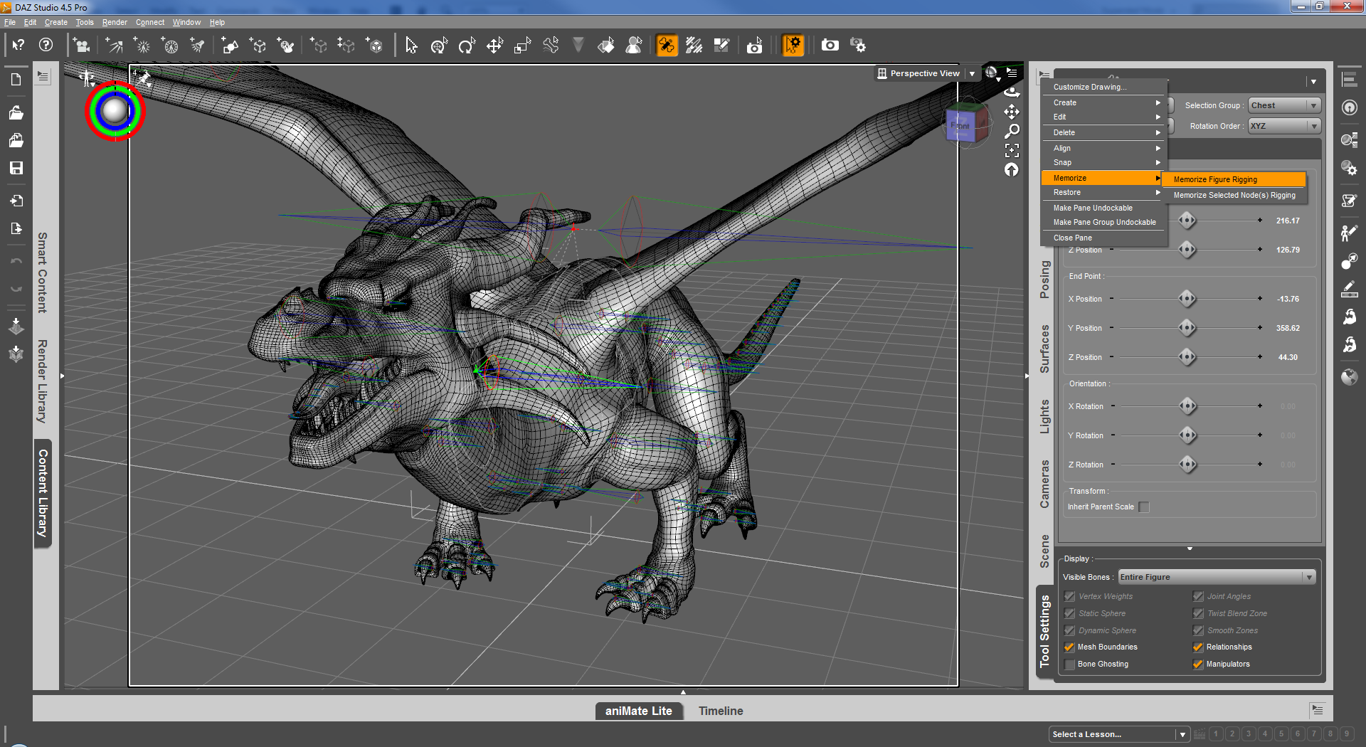 Under the Tool Settings at the very top left there is a pointer, open that up to find a menu, choose Memorize, Memorize Figure Rigging (See Illus. 12) This step is very important, you can edit the bones later, but it must be done or the bone placement may be lost on saving.
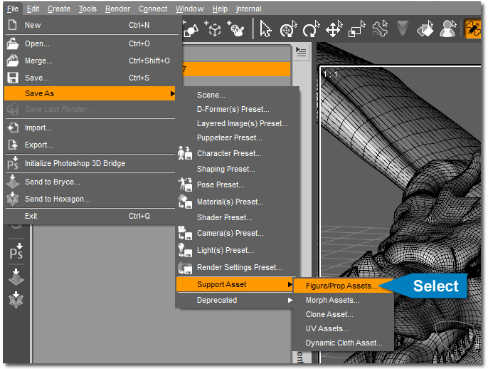 Save the figure. File > Save As > Support Asset > DSF Figure or Prop File. (See Illus.13)
You can still edit the rig at any point after the memorize, even after saving the figure. Bones will still need adjustment in the joint editor after figure set up. Figure set up gets you part way there. The final work for the bone set up happens in the Joint Editor.
 The Figure Set Up Tool Places the bones in a straight axis, but you will find areas of the model that are not aligned to work with a straight axis and will need adjustment. (See Illus.14) An example would be the Dragons tail. It is not modeled straight back on the Z axis in a perfectly level line. In is modeled in a more natural state, more of a relaxed S curve. In the joint editor we can adjust the center points so the bones follow the curve of the tail.
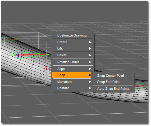 Here is a list of tools that assist in that task. They can be found if the Joint Editor is open, and by Right Mouse Clicking in the scene. (See Illus. 15)
The tools that are most useful here are:
Found Under the Align Option:
Found Under the Snap Option:
The work flow for setting up the bone rigging consists of moving or rotating the bones to follow the angles of the geometry of the model. The dragon model has a curved tail and neck. The Figure Set Up room creates bones that align along the x, y or z planes be default. Sometimes this works, as in the dragons chest, and sometimes it does not. In that case, adjustments need to be made to the bones.
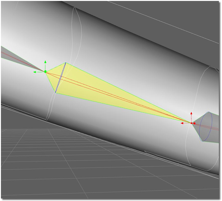 Each bone has a manipulator at both ends. The Red point at the narrow end of the bone is referred to as the End Point. The Green point at the broader end of the bone is referred to as the Center Point. (See Illus.16) The Center Point is the Pivot point of the bone. The center and end points can be moved by using the manipulators and the ends of the bone. The Joint Editor Tool Settings can also move these by using the sliders, or by typing in numerical values.
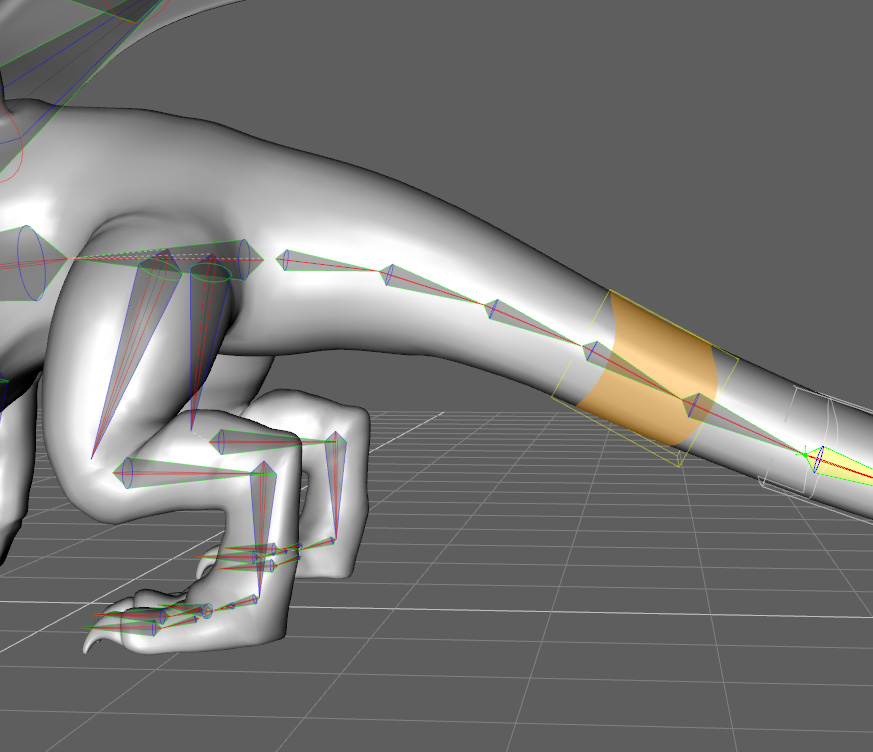 Changes can be made on the bone's rotation, to more closely match the angles of the tail, neck and legs of the dragon. Here is an illustration of the finalized bones. Note how they follow the angles of the geometry in to tail and legs. (See Illus.17)
There is a video which goes into detail about the Center and End Points. While it is for an older version of DAZ Studio, the principles are still very useful. It can be found here: Figure Setup Tools: Joint Editor - Center and End Points.
If the model is symmetrical, and uses correct left and right naming conventions, adjust the bones on one side of the model, and then mirror them over to the unfinished side. (This works in the case of the wings and legs of the dragon.)
When manipulation on the bones is finished to be in the position needed for optimal bending, Memorize Figure Rigging. Viewport Tool > Joint Editor > Tool Settings Option Menu > Memorize Memorize Figure Rigging. Make sure to do this before saving your figure, or your work may be lost.
At this point, you should have your figure prepped and the skeletal bone structure set. Now it is time to move on to Basic: Weight Mapping a Figure (WIP).
To return to Part I of this series:
